• Home
  • My Work
  • My Services
    • Antenna Design
    • Antenna Tuning
    • Antenna Testing
  • My Stuff
    • Testimonials
    • Clients
    • Patents
    • Projects
    • About Me
  • Contact
Antenna Design and TestingAntenna Design and Testing
  • Home
  • My Work
  • My Services
    • Antenna Design
    • Antenna Tuning
    • Antenna Testing
  • My Stuff
    • Testimonials
    • Clients
    • Patents
    • Projects
    • About Me
  • Contact

Antenna Design

The design of the antenna is wicked important.

No other part of a wireless product is as critical. Regardless if these other parts work great, poor range and unreliable communications will ruin the products perceived value. Antennas can be created in a wonderful variety of different types, shapes and sizes to suit virtually any application. The tricky part, however, is balancing radio range, cost and the amount of available space inside the product.

Design Trade-Offs

Operational Range

Radiation Efficiency

Manufacturing Cost

Available Product Space

Battery Life/Size/Cost

Time-To-Market

As shown above, antenna design trade-offs are interrelated. Changing one variable impacts the others.

  • Large antennae may have better range but may be more expensive and require more space in the product.
  • Small antennae may have less range but may require more power and have shorter battery life.
  • Depending on the range required, antennae can be designed to be tiny, cheap and require little energy.

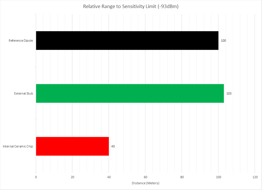
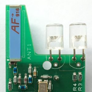
The above is an apples to apples comparison between a control reference antenna, a stubby external antenna and a internal ceramic chip antenna. Although the external stubby antenna was more expensive and required more labor to install, Range Testing conclusively proved its superior performance in this application. This convinced the client the cost was justified and solved his range and reliability issues.

Conversely, Range Testing in the field may prove that a small internal antenna is more than sufficient for the application.

Innovative Design

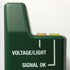
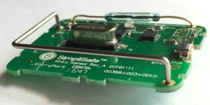
This is an example how the optimum location for the antenna became a product feature.

Major Antenna Types

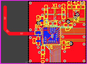
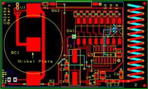
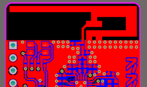
PCB Trace Antenna

The PCB Trace Antenna is simply a copper trace on the PCB.

It can be designed into various shapes and sizes depending upon the available space on the PCB.

A zero-cost solution, it can be effective for close range applications.

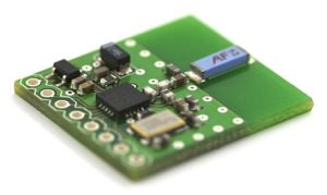
Ceramic Chip Antenna

In addition to a small footprint, a significant feature of the Ceramic Chip Antenna is a wide bandwidth.

Important with portable products, the Ceramic is less subject to de-tuning whilst hand-held or when placed upon metal objects.

Although manufacturer’s do offer general purpose designs, careful placement and tuning is still required. They are not cheap.

Bent-Wire Antenna

The Bent-Wire type is simply a stainless steel wire formed into various shapes by machine.

Made from “Spring-Wire”, these are quite rugged and will retain shape even if dropped hard.

Low cost in high volume, these can out-perform PCB types.

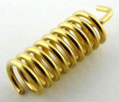
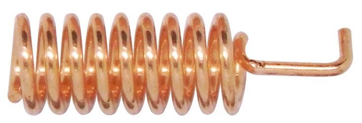
Helical Antenna

The Helical Antenna is a elemental antenna type and is basically a shortened whip coiled as an inductor.

It performs better than most PCB antennas but requires more space in the product enclosure.

These can be manufactured quite economically and are frequently employed when an external antenna is not wanted.

Helical PCB Antenna

The Helical PCB Antenna combines the high performance of a Bent Wire or Coil type but in a low-profile zero-cost configuration.

Actually a 3D structure, it stitches together the top and bottom traces creating essentially, a flattened coil.

Circularly polarized, it is compatible with both horizontally and vertically polarized antennas.

External Antenna

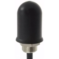
An External Antenna is sometimes required for operational range or when no internal space is suitable.

Generally, even a small External Antenna will perform better than any PCB trace type.

These can be very small and be designed to be quite inconspicuous.

Inverted F Antenna

The Inverted F Antenna is a compact and efficient PCB antenna.

Producing an almost omni-directional radiation pattern, it is frequently employed in cell phones.

It requires no additional components to mate with most standard radio chips saving both cost and PCB space.

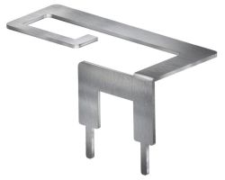
Stamped Metal Antenna

The Stamped Metal Antenna is employed when objects on the PCB create significant interference with the RF radiation patterns.

As shown here, it approximates a Inverted F Antenna but is elevated above the PCB.

These are usually only found in higher end products as the development and material cost can be expensive,

Antenna Design

Antenna Tuning

Antenna Testing

© 2025 · Zebryk Engineering